Tuesday, March 17, 2015

Kato MP36PH mechanical issues

The Kato MP36PH is a good looking locomotive; it is also the first Kato I own with the new drive mechanism, and for the most part it was not a problem. At first…

It started (or I noticed it) when I pushed the locomotive forward over a rerailer. None of my other locomotives rolled! And the sound was unmistakable; there was some slipping going on.

From then it got progressively worse; as I added more cars to the train, going up a grade, or accelerating from a standstill. It would occasionally stop, with what could only be described as a grinding sound from the drive train. Usually turning off the power would correct it, and it would be OK.

And it kept on getting worse, i.e. more frequent.

After digging for reports of problems on line, and finding none, I took the plunge an called Kato in Chicago.

Apparently some of the first models had "too tight of tolerances" in the drive train, and it would slip as I described. I could ship the locomotive back to Kato for a repair, but I preferred to get the parts and do it myself. After what seemed like absolute ages, they finally arrived. But then I managed to misplace them, or leave the train elsewhere when I planned to repair it, or leaving the replacement parts in a box of tools on the other layout.

Yesterday I finally broke down and repaired the locomotive yesterday the task daunted me a bit...

Well, it was not all that hard.

One key bit of advice from Kato: "Keep the new frames separate from the OLD frames. Theu look identical..."

And this is very true!

The doing:

The one-piece truck frame is flexible enough to pry far enough apart to let the gears drop out (after removing the axles), but be careful to keep them separated. The three lower gears appear to be identical, and from there the worm gear and idler are easy enough to tell apart.

Why is this so important? The trick is to put them back in the correct sequence:


From the top of the truck frame, insert the small idler gear that sits beneath the worm gear

Then the worm gear

The lower "middle" gear

The two outer gears that drive the axles

Of course, fitting the truck and the contact strips into the side frames is a special challenge, but with time and care it slips back after a few tries.

I finished this up about 11:30 p.m., so only a short test run to confirm success was made. I will try to get some filming done tomorrow.

I know it is better as you can't push the locomotive and hear the gear slip noise you used to hear. It even sounds a little quieter under power...


Sunday, April 20, 2014

Servo Turnout Motors On Foam Layout Boards

I have been fascinated by the use of radio-control-style servo motors to control the turnouts on the layout; but so far I have been having trouble deciding on the best way to go. The control products, and SwitchWright by Tam Valley Depot (http://www.tamvalleydepot.com) were leading the pack, especially when combined with a frog juicer to automatically route the power to the frogs (one practically “need to have” with hand-laid, Micro-Engineering, Shinohara, and Atlas Code 55 turnouts). The  SmartSwitch by ANE Model (http://www.anemodel.com/) gave me just enough doubt to not rush in, and I recently stumbled across Iowa Scaled Engineering (http://www.iascaled.com/) almost by accident, and have actually gotten one in to try it out!

The product that caught my attention:

MRServo-3: Slow Motion Switch Machine with PowerFrog Technology

"MRServo is a low-cost, low-profile, slow motion model railroad switch machine featuring PowerFrog technology. Using inexpensive and small RC servos, MRServo provides a cost-effective way to add slow-motion turnouts to your layout. PowerFrog technology provides a reliable, short-proof way to route power to solid frog turnouts. (Examples: handlaid, Peco Electrofrog™, Shinohara™, and Walthers™ models.) These turnouts will create a short if the points make contact with the opposing rail before the contacts driving the frog switch polarity. Traditionally, the solution has been to add additional gaps in the point rails, isolating just the frog. With PowerFrog, this is no longer necessary. When MRServo starts to throw the points, it momentarily isolates the frog. Once the servo completes throwing the points, it sets the direction relay to the correct polarity and, after a small delay, re-energizes the frog."

All well and good. But one thing that has yet to be answered through any of my “intense planning” (a fancy name for procrastination) is: “how to mount the servo on a foam-board layout?”. I searched the web for many weeks, but every example is either hard board or plywood roadbed. I have tried the Peco twin coil motor with a auxiliary contact unit, but as the motor is twice the width of an N Scale turnout, AND mounts directly to the turnout itself, I had two issues:


  • The size of the installation would not work for the most-crowded locations on the layout. Here is one example where I would like to use the powered turnouts, but would have severe trouble mounting the motors because of their size:


  • The mounting method, with the motor fixed to the turnout itself, did not leave me very happy. Part of the aesthetic drive in me could not accept the visibly obvious mounting, even when covered by a piece of card. The left-most turnout in this picture is one of two examples:


Having toyed with the idea of adding a firmer covering between the motor and the turnout, and continuing the cork sub-roadbed (while I don’t go crazy ballasting around turnouts, I do try to make it look like I have when possible) to maintain the appearance.

Solution found in other projects:

In a couple of places I have used foam-core board to solve clearance problems. The board is fairly sturdy when supported adequately, and does not warp or swell with the changes of the weather. A slight downside is the fact that the board is covered with card, and while it is water resistant, it is not completely waterproof. I would recommend sealing the board prior to applying scenery using water-based adhesives.

Another option would be to use a piece of Masonite, but the advantage in greater rigidity would not offset the ease of working with the foam-core. If for any reason I find the foam-core inadequate, I can easily change to the Masonite mounting using the same methods I will describe here.

Planning the installation:

I used the turnout planning products available on Peco's website (http://www.peco-uk.com/page.asp?id=pointplans) to determine how much space I had to work with especially considering the crowded arrangements in a few places.


As the Circuitron Tortoise and Peco motors both have a significant footprint, and extend under the adjacent track areas, a “better” solution must allow use under the crowded parallel tracks. Alternating the smaller servo motor’s placement (left or right of the center-line, or towards the frog or away from it) would allow for closer spacing, and only a few places would require careful planning. Based on the spacing between the tracks, I settled on a one-inch by two-inch sized panel for the smallest installation. I proceeded on the assumption that scaling up to a larger panel would not add problems, and a successful test on the smallest size would be conclusive for all.

Changes to "Normal" mounting plan:

One of the advantages for the size of the servo was that it is not much wider than the track itself, so if the servo could be mounted on its edge, a much closer mounting could be possible. But to do so would mean making changes to the unit itself, and again, if it worked, great, but if not (and I find I have been making a mistake!), I could still mount it in the “traditional” side-mounting method.

Using a razor saw and file, I trimmed the original mounting lugs from one side of the case. To achieve as smooth a surface for the mounting tape as possible, I used a very fine emery board to smooth the cut marks in the plastic case.


The placement mock-up would theoretically work, so I proceeded with the plan to mount this unit as shown below:


Fitting:

Using the board to mount the motor in the foam board requires a hole to be cut; cutting the hole with a lip to hold the assembly level and at the same level as the top of the foam will reduce the visual impact and make the mounting much firmer. The nature of the assembly allows for a greater degree of flexibility in how to do so, allowing the profile of the surrounding track to be carried through the mount. So far, only the servo option offers the reliability to mount the assembly in such a manner.

The mounting hole is cut large enough to allow the motor to sit below the track level, with an adequate lip to support the mounting board:


I cut the hole using a disposable knife, which allows the blade to be extended and trimmed for renewed sharpness. The length of the blade allows cutting completely through the foam, and using the entire long, sharp edge to make the cuts.

Once the hole is completed, I used an X-acto knife to cut the lip for the mounting board. Trace around the edges of the mounting board with the X-acto knife, to ensure the hole is no larger than it needs to be. Make horizontal cuts up to the edges of the mounting board’s dimension. On a larger installation you could use a piece of the mounting board as a spacing gauge, but I used small cuts to make gain the desired depth, testing occasionally to ensure I did not go too deep.

The end result:


Test fit the mounting board into the hole, and verify the depth is only as deep as needed.


Track preparation:

With the mounting board in place, I fastened the cork sub-roadbed. In this installation the cork was installed in one section. I applied glue (PVA, or polyvinyl acetate), ensuring that the gap between the mounting board and the foam is kept free of the glue. I used the same plastic topped push pins I use for track laying to secure the cork while the glue dried:


This example shows the sub-roadbed for the turnout, illustrating how I prefer to add the diverging route:


I use a full strip for the primary direction (which may be the diverging route) and add the second strip to the other. This way the primary route has the most solid base.

Once the glue has dried, I used an X-acto knife to cut the cork on the sides of the mounting board, and remove the board:


The Peco turnout does not have a hole in the throw bar for the piano wire to go through, so I carefully drilled a 1 mm hole centered between the point rails. I cut the hole for the throw wire by using a small drill bit to open a hole centered on the turnout. Then, I used an X-acto knife to enlarge it, to allow the steel wire to move freely side-to-side:


From this point I followed the standard instructions, securing the motor in place below the turnout.

First, I mounted the board with the motor installed, testing that the throw wire moved freely from side-to-side before the glue dried.

When I laid the track, I also glued the turnout in place with PVA, avoiding any moving parts. The throw wire has more than adequate travel to compensate for any shifting or required variation form the plan, and allow proper operation.

Should the motor ever require replacement, the foam board and foam-core board are easy enough to cut through to cut the current installation out and make new cuts to mount a replacement motor (or remount the original one), but using a completely new mounting board.

Once everything is dry I connect the power and try it out. The example shown is an Insulfrog turnout (it’s a long story…), so I did not test the power routing. This was purely an exercise to validate the mechanical aspects of the project. I’ll post a follow up, and maybe a video, of it in action.

Sunday, March 16, 2014

Heavyweight Passenger Car Upgrades - Wheels of Time 999009 4-wheel Heavyweight passenger truck

I undertook a test-fit of some of the first Wheels of Time heavyweight four-wheel trucks to a very old Bachmann combine, and it was not a simple swap-out.

- the truck crossmember (I'm sure it has a name) sits a bit higher than the original Bachmann truck, necessitating some body work to lower the car

- the kingpin supplied was much larger, so a 2.5mm hole had to be drilled (the original hole enlarged) but it does look like I can drill the center of the pin to run magnet wire for lighting

- the lowered floor may play havoc with coupler height. Need to do some proper measuring to be sure.

But they do look pretty good:


Bachmann combine with new truck on the coach end


Comparing the original (left) to the new (right)

I'm not 100% sure it is worth the work on the newer examples of the cars. I may complete this one, and see how it compares in use to the others with "as is" trucks. Those with older plastic wheeled trucks need at least new wheels, so we'll see.

Once I make a final determination I'll post a thread; I may also attempt to convert a Micro-Trains RPO to the four wheel truck, as a lot of the pictures I have show this instead of the six-wheel truck...

Tuesday, April 2, 2013

Evolution of a Favorite III

I can say I am very happy to find a like-for-like replacement for another article of despair for N Scale of old. Considering how new the scale was when this car was released, we were really blessed to have the variety of passenger car styles we did have. Unfortunately, some were less than faithful reproductions, and some were just mechanically under engineered. This example fits into the latter category.

The prototype is a fairly faithful example of a C&O Pullman coach that saw service in the “aftermarket” on D&RGW, C&NW, and SP:

“The car is in two sections divided in the center.  Fifty-nine coaches in the 1610-1668 series were delivered to the C&O by Pullman in 1950 for service on most C&O trains, including the George Washington.  Eight of these cars were sold to the D&RGW.  Good photographs of this car are on page 8 of Chesapeake and Ohio color guide to freight and passenger equipment.  C&O removed the corrugations in 1967.”


Amtrak? Not too sure how authentic it is, but it was different from the smooth-side coaches offered:


Later, rather recently, it was included in the Centralia Car Shops production as well:


Comparing the two only shows the limitations of “good enough” when the Con Cor version was released:


The main problem was mechanical; the trucks were held in place by plastic clips molded into the sideframe. And they liked to break off, leaving the truck almost useless. Sure, you could fill the hole in the body, and use a screw, but it wasn’t the strongest link in the car’s chain by far.

The other disadvantage was trying to light it, like all other Con Cor cars (until the later Rivarossi re-brands), was practically impossible. The CCS car offers this ready to run, and for once, I am almost pleased with the effect. I have been pretty cruel to the result in other cars, as it looked far too dim. But in this case, it does look pretty good:


Next time?

Wednesday, April 4, 2012

N Scale GP7 Chop Nose Conversion

I've wanted one of these for a long time; as I was growing up we saw many GP7s, GP9s, and even a few GP18s alongside their newer brethren.  We've had lots of GP7 and GP9 models (and even two variations of GP18!), but one problem:


This is the usual reality.


Our models though are ALL high hood (with one rare exception from Canada of a Life Like chop-nose GP9).


So after looking at available parts, I realized that short noses and cabs from two different SD models would work. I even built a mock-up using an old GP9 shell (for the really old 1980s Atlas version) to see how it would all come out.


Today I took the plunge. Here's the first ever view of the end result:


and head-on:


Work involved (in VERY condensed version):


- Disassemble the GP7
- Trim the frame at the front to clear the low nose; it's a bit too tall.
- Trim the high short hood from the GP7 body. I had to trim the 'gap' that the cab sits in to allow the cab to fit low enough on the body. There is a structural difference between the stock and new cab.
- Remove the short hood from the SD cab; I will do this slightly differently in the future for better mounting
- Reassemble the frame AFTER a thorough cleaning.
- Test run the frame
- Replace the lower body (walkway and frame).
- Fit the long hood in place
- Fit the short hood in place
- Fit the cab in place
- Show off


I've got to get good enough at painting, hopefully over the summer, and then letter it. Weathering of course after "new" photos. Then on to GP9s. And GP18s. And SD9s. And SD7s...

Tuesday, March 27, 2012

Six steps to a better N Scale Caboose

Improving (correcting!) the truck centers on Atlas "second generation" caboose models is a fairly simple and straightforward task; once you start though you will need to complete all of the major steps in order to run your caboose, so hopefully you are comfortable with doing the entire job.

With the relatively good supply of cheap 'victims' this is a good project to gain confidence on. Once you complete the frame modifications you might choose to go on to other 'improvement' areas, but I'll leave those to you. I personally have not done any more, but will probably replace handrails and ladders at some point, if I can match the color of the paint!

1. Identification – or how do I know my caboose in incorrect?

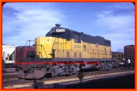
Not all models are the same; this was one case where Atlas originally did things right, and in a 'newer' version made a mess of things. Maybe one day we'll know why. But for now, compare the photo of the prototype caboose (very dang close to the model):


(Photo is from http://www.girr.org/girr/lals/lals_facilities.html I can recommend a visit to this club if you are in Los Angeles, as it is AWESOME!)

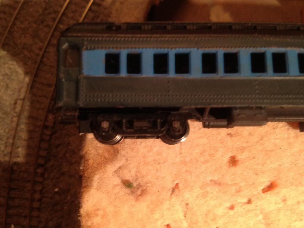
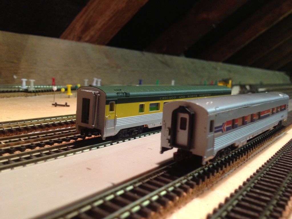
To the photo of the model:

One of my older, but not oldest, Atlas cabeese.

Notice how the truck actually sits up under the steps, and the center (which signifies where the bolster is) does not line up with the nub under the right hand window. An earlier caboose I have has this correct, as well as having body mounted couplers, dating back to the late 1960s! Well ahead of its time for certain. Just one of those annoying things that Atlas did during the 'tween' years that drove a few people I know away from N-Scale.

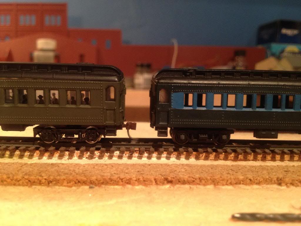
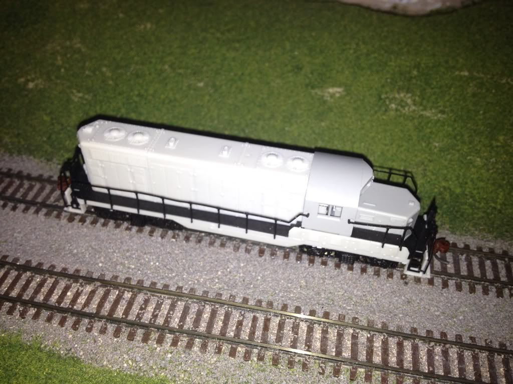
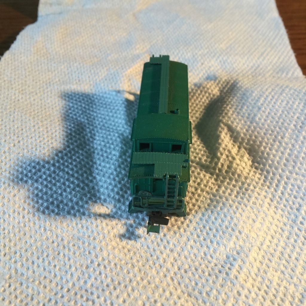
Below is the "original" (bad paint job and all; what was I thinking!) version of this caboose, albeit with Micro-Trains trucks attached...


This is the look we are trying to achieve, as it is mechanically correct for how the caboose should be.

2. Disassembly

I removed the trucks, the floor from the body, and removed the end rails/ladders to keep them safe. The weight will become the inner floor, and I re-used it to both keep the plastic floor pieces in alignment and to give it strength. You could decide to use a piece of rigid sheet plastic styrene, and cement the floor pieces to it, but in my mind that raises the center of gravity and I was not happy with that. My approach has held up well (until I took it apart for the photos), so it really is down to preference.

3. Floor (frame) modification

With the caboose disassembled, it is time to start cutting.

I made four cuts total, two for each bolster, so that I could turn the bolster section 180 degrees to realign it. "Where" to cut is pretty flexible; in my case I cut almost up to the line where the bolster 'should' be, and as close to it as I was comfortable cutting on the other side. This produced a section like this:

I cleaned up the section with a file and modellers sand paper, and (possible incorrectly) trimmed off the frame section in what is the left hand side of this piece. Later, after looking at photos and drawings of prototype cars, I discovered that perhaps this should have been left in place, and extended to the coupler draft gear area. The resulting gap seems unrealistic.
Drawings of a prototype or actually seeing one in person would have been a big help, but being several thousand miles away makes seeing the real thing tricky at best, and 'pre-Internet' modelling was a bit of a pain in some cases too...

Once you are happy with the cleaning up, test fit the floor pieces to ensure they will all fit. If you manage to get the cut out sections swapped end for end, you might have trouble unless they are reasonable similar sized.

I replaced the end floor into the caboose body (I think I used ACC (super glue)) to fix the weight in place, and then pieced the other sections in place to line them up. If the bolsters will not center on the side nubs (I should really learn what they are called!), trim a bit more off the appropriate section to make everything fit. 


See below:


If the bolster sits too far out towards the end of the caboose, trim from the center section instead of the bolster piece, to avoid trimming too much off the bolster itself. On the other end it really does not matter, as this will be out of sight anyway. I have already attached couplers when this was taken, but would do it after the floor was assembled and dry.
Once you are happy with the alignment and fit, attach the three center sections with ACC (super glue) and let dry. I considered using styrene pieces to cover the gaps, but decided against it, as they would do more harm than good visually.
4. Coupler mounting

Coupler mounting is pretty much a standard job; you might need to shim the coupler box down from the floor, so make sure you have decided what to do about the trucks first.

5. Truck modification

If you are happy with the standard truck, all you need to do is remove the coupler box from the truck frame and re-attach. Me, I decided on some of these that Micro-Trains (part 00302140) "Swing Motion" or Atlas (part 22060 for friction bearing, part 22061 for roller bearing) Caboose trucks. I will eventually fit Fox Valley Model's metal wheels, but for now these have whatever was in the trucks I got/had on hand. The IC model still has the original Atlas trucks (as far as I can tell).

6. Re-assembly


Another great area of improvement would be to paint the handrails, and if needed, the roofwalk. These items were often cast in black plastic, and not painted, no matter what the road scheme of the caboose was!

Compare this (different model) ICG caboose:

Notice that the color of the end railings, steps, and even the draft gear matches the body color of the caboose! This is one of the simplest “fix ups” you can do with your equipment to eliminate the “toy like” appearance that is, or thankfully I can say, was, a common occurrence in the hobby for many years.

The color does not have to exactly match the body color for many reasons, such as repairs, aging of the body or railing paint, application of “safety” colors (such as white or yellow). A reasonably close mix can often be made, to avoid repainting and re-lettering the entire car. Additionally, weathering makes a wonderful disguise for the variations in color or finish, or to hide any minor mistakes that might happen during the modifications or decorating.

While doing these paint “fix ups”, don’t forget your other rolling stock. Some freight cars may have minor accessories that can benefit from the paint touch up, one of the most common being roof walk, draft gear box, or brake wheels.

Case in point:


I painted the end platforms and ladder assemblies of this Minitrix body to demonstrate the improvement it can make; compare the results to the Illinois Central car of my project, and the prototype photo above.

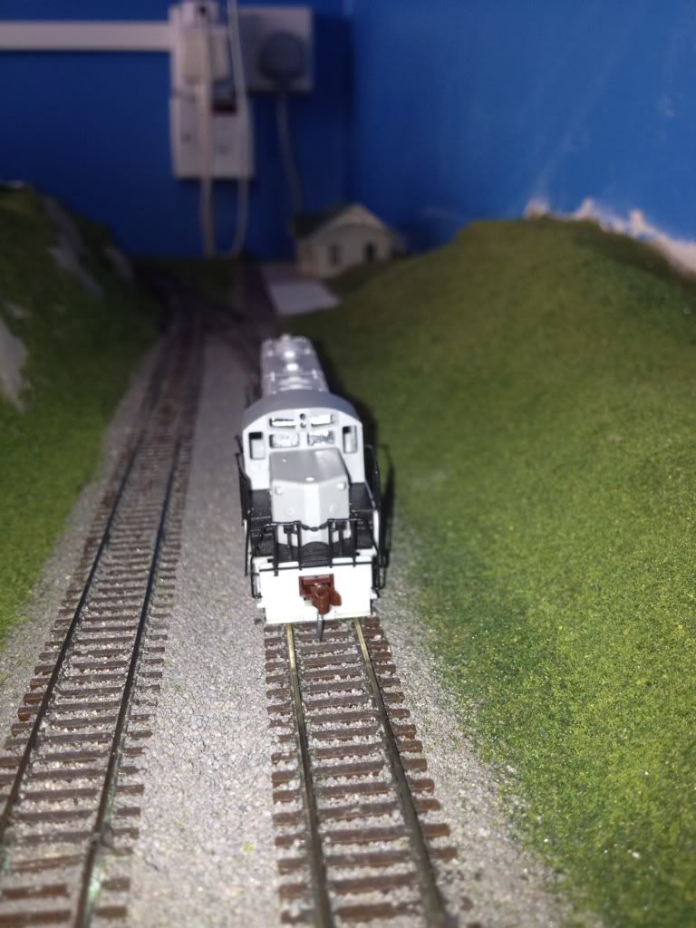
Re-attach any details, and sit back and admire your work. That wasn't so bad, was it?

A view of a completed model; hopefully you can see the difference!


Note: I originally wrote this for an N-Scale community site several years ago. The abundance of better quality models has made this kind of project less appealing for some, but there is no reason why any modeller should be afraid to make simple modifications to rolling stock, especially if it helps them reach a particular goal, such as an unusual or unavailable prototype. These older caboose models can often be purchased on line or at model train and toy sales, and I as I mentioned, are great "first" projects to gain confidence on. Feel free to leave a comment or contact me (you may need to register first) if you have any questions.

N-joy!